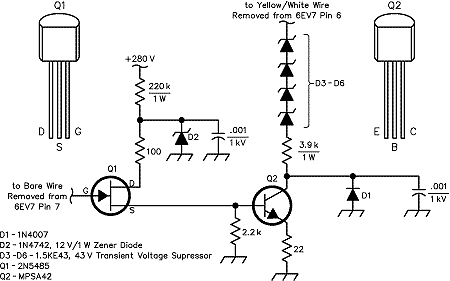
Figure 1 |
Walt, WA1KKM, found himself in a bind during a recent contest when the keying relay driver tube--a 6EV7--in his Drake T-4XB transceiver failed (in transmit mode, of course). He offers this solid-state replacement by way of demonstrating some ham radio ingenuity: The 6EV7 has become difficult to locate, and I did not have a spare when it failed during the 1999 ARRL International DX Contest CW weekend. Since the phone contest was only two weeks off, I needed to design, build, and test a control circuit in a hurry! This meant that everything I needed had to come from the junk box, which explains the somewhat unusual design (see Figure 1).

Figure 1 |
This circuit replaces one side of the 6EV7 dual triode. For those not in a hurry, components are inexpensive and available from various mail order suppliers. This should give you some ideas about what can be done to replace "hollow state" devices that are in short supply these days.
The high source resistance of the control voltage required the use of an FET input stage for this control circuit. The 2N9485 has a cutoff voltage Vgs = -4 V, so it's ideal for this application. Many other popular FETs have much higher cutoff voltages and may not work in this application.
The 220-kohm resistor limits the current through the FET, Q1, to about 1 mA, while D2 prevents the full 280 V from appearing across the device. The high-voltage bipolar transistor, Q2, has a maximum voltage rating of Vce = 300. Since the supply voltage of 280 V seemed too close to the maximum rating for the FET, I used four 43 V transient voltage suppressors (D3-D6) as zener diodes to drop the voltage across Q2 to about 110 V.
In receive mode, the -5.5V control voltage cuts off Q1, which removes the base current from Q2, cutting it off and opening the relay. In transmit mode, the 0 V control voltage allows Q1 to conduct, providing Q2 with about 1 mA of base current. This causes Q2 to saturate and closes the relay.
A couple of notes: The relay (not shown in the schematic) has one side of its coil connected to +280 V. The other side of the coil is connected to the far end of the yellow/white wire. The coil resistance is 5kohms. The coil draws 12 mA (transmit).--Walter J. Legowski, WA2KKM; sue_and_walt@compuserve.com