FT-1000D Synchro Mod
If you have an FT-1000 with the BPF-1 option, and are into HF weak signal DXing, this is for you. Although not for beginners, it should be no problem for
hams with some home building experience. This simple 'no-holes' mod adds a lot of functionality, yet requires little more than a DPDT 5V relay. It
synchronizes the tuning of both the main and sub receivers to the main tuning knob, making antenna diversity reception so simple and painless that you
will wonder how you ever did without it. Diversity is a powerful technique- the increase in intelligibility and reduction in operator fatigue often border on
amazing!
From the Yaesu FT-1000 Operating Manual, page 31:
"...the vast potential for optimizing reception of different signals using diversity reception with the FT-1000 is largely unexplored. We invite you to
experiment with these modes, and we hope you share your findings with others..."
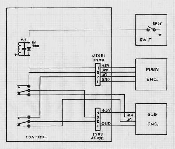
Schematic: The Main encoder connects directly to Control board connector J5031 as before- its MDØ1 and MDØ2 signals are also cabled to the relay
N.O. contacts. The SDØ1 and SDØ2 signal paths from the Sub encoder are broken and the relay is inserted in series. Connector J5032 is normally switched onto
the Sub encoder- when SPOT is pressed, the relay operates and J5032 switches onto the Main encoder in parallel with J5031. The relay coil can pick up
5V from either connector. Note that this is a 'no-holes' mod using added connectors, and is easily reversible!
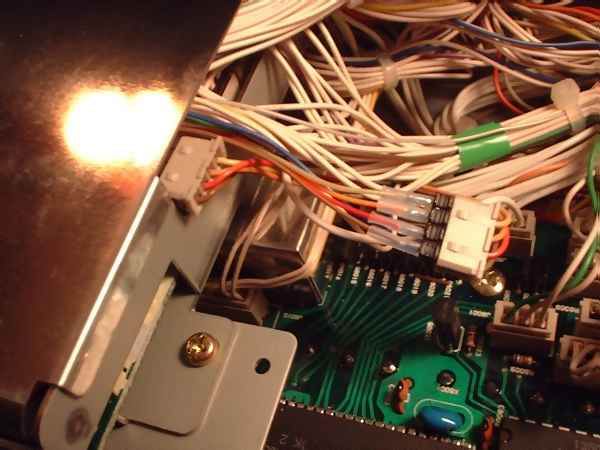
Photo 1: My version of this mod is connectorized- added headers provide accessible solder points for connecting to the Ø1 and Ø2 encoder signals, +5V,
and ground. The main and sub encoder plugs are pulled from their connectors on the Control board and reconnected through a simple wiring harness. The
radio can be quickly restored to its original configuration by simply replugging connectors. The main encoder plug, visible at the right edge of the shield,
connects directly to the board using a home-made right-angle adaptor. The sub encoder plug 'floats' outside the enclosure on the harness. Note the
snug-fitting teflon sleeving over the solder joints on the floating header.

Photo 2: The relay shown is a low profile Omron G6A-234P-ST with sensitive coil. The body is about 0.325" (8.26mm) high. I also verified that standard
size DIP relays about 0.450" (11.4mm) high will clear the cover. I used #26AWG solid wirewrap wire in colors consistent with the Yaesu harness. The
yellow wire brings +5V over from one of the connectors (relay top left), and the gray wire comes from the SPOT switch (relay bottom left). These two
wires were woven into the original harness bundle for added mechanical support. The diode and capacitor, not shown in this view, connect across the
coil terminals on the left.

Photo 3: Relays, crystal filters, and other larger components usually need to be secured to a mounting surface in some way. Because I was in a hurry to
try the circuit, I took a thin piece of foam packing material and pressed it onto the relay PCB leads. This made for a snug fit under the shield cover and
locked the relay in place against the PCB. Care must be taken to insure that the exposed PCB terminals cannot contact the cover. If you think you might
send your radio back to Yaesu for service in the future, a foam block might be a better method than double-stick foam tape. For this purpose, the foam
material must be soft and easily compressible, not rigid like styrofoam. It should exert only a slight pressure against the cover and PCB. Note that the
relay cannot be bonded to the inside of the shield because the mating cover has a flange that fits down inside the shield.
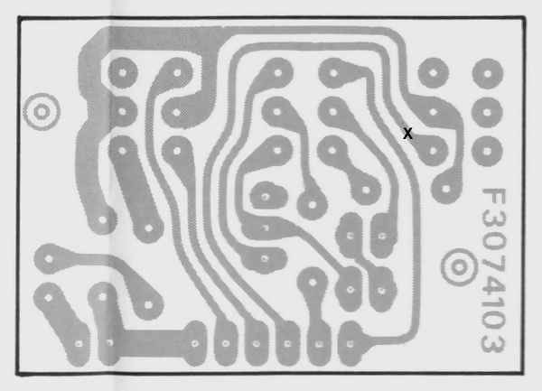
Pictorial 1: This is a view of the SW F PCB containing the SPOT switch, as seen when the front panel is hinged down. The "X" shows the approximate
location where I made my track cut- actually it may be cut anywhere between the switch and the connector pad shown at bottom center. The solder
point for the wire connecting to the relay coil is the round switch pad just below and to the right of the "X". This point grounds when the SPOT switch is
on, energizing the relay and enabling 'synchro' mode. If a PCB track cut is unacceptable, a 'no holes' alternative might be to pull out connector P8805
and slip pin 3 (SPOT) out of the housing, insulate it, and bend the wire back out of the way.

Photo 4: The SW F board is visible in back of the Shift/Width control. Note the gray wire connected to the N.O. terminal of the SPOT switch. The track cut
is visible to the left of the wire connection.
Parts List
-
Relay, DPDT, 5V, Sensitive coil Omron G6A-234P-ST (5V), Omron G6A-234P-ST-US (5V), NTE R40 series- Mouser P/N 526-R40-11D2-5/6, Aromat DS2E-S-DC5V (Try Digi-Key), or
equivalent. Rcoil approx. 125 ohms or greater, Pcoil approx. 150-200mW (to minimize added load on the 78L05 regulator)
-
Header, 0.025" Square Post, Female, 4 Postion (need 2) FCI "Dubox" 68685 series- Needs to be cut to length from longer connector and the end filed smooth- Mouser P/N 649-68685-3xx (substitute number of
positions for "xx"- 06, 08, 10, 14, 16, 17, 18, or 20) Also need to file 45º bevels in two corners to fit connector shroud on Control PCB
Header, 0.025" Square Post, Male, 4 Position (need 2) Circuit Assembly 36 pos. single-row, straight PC strip line plugs- Mouser P/N 544-CA-S36SP100 (Designed to be snapped apart into needed lengths)
-
Diode, Silicon, 1N4001 (or similar) Protects against transient voltage spike from relay turnoff. Install right at the relay coil.
- Capacitor, 0.01 uF
- Hookup Wire
- Tywraps, White Plastic, 4" (optional) For cable lacing
- Teflon Sleeving (or similar) For insulating solder tails on sub encoder header
- Tape, Double-Stick, Foam (alternative: soft foam sheet)
Synchro Mod User Tips:
-
Both the main and the sub receivers may be independently programmed for band, frequency, mode, and bandwidth while in Synchro mode. The two will
continue to track at the same tuning rate. You can return instantly to Diversity mode at any time by punching A>B.
- Slow day on the bands? Propagation not so good? You can monitor two different bands simultaneously. For example, enter 24.890.00 in the main rx and
18.068.00 in the sub rx and tune around both bands using the main VFO- or try 24.890.00 + 24.930.00- you can monitor both the phone and CW segments
on a band.
G3TKF