Drake L4B/8877 Retrofit Projects
An Overview and Perspective
By
Ronald
Lumachi, W2CQM
You may recall that there’s a chilling bit of dialogue in the classic movie Poltergeist that’s particularly memorable and remotely related to this posting. It’s the scene when the little girl announces “…They’re back!” when she sensed that the hated spirits and goblins, which were thought to be exorcised, had returned. I guess the same can be said for me, and not unlike General McArthur, I too have returned with a second and then a third project in the series of L4B/8877 HF retrofits: What’s fascinating about the venture is that on one level it created heated discussions about its relative value and appropriateness; and on the other extreme a full range of support for the project. When completing the first 8877, I vowed to myself that I’d never undertake a similar project, based primarily on the amount of labor involved. However, I did, almost immediately, change my mind simply because I realized that in hindsight and with the rebuild experience under my belt, I could easily and more quickly duplicate a more potent powerhouse amp the second time around with the vintage Drake L4B platform. I felt confident that I would be able to further refine the endeavor with an even more compact amplifier with higher power levels with only a fraction of the labor to make it materialize. I’m now convinced that there’s something to be said for success and its effect on one’s ego.
The first Drake 8877 project netted a certified 1800 watts into the dummy load as verified by a pair of Bird 43/4410 wattmeters. Not too bad for the old gal! The Drake developed considerably more power than the original pair of 3-500’s and was comfortable in her new role. What I did find from the preliminary testing was that the tube had grid current to spare but I couldn’t squeeze out another drop of RF no matter how I tweaked the controls. The maximum power level problem was immediately traced to the selection of the bargain priced hamfest purchased Alpha plate transformer. The voltmeter confirmed its sagging voltage output under a heavy load. Unfortunately, the transformer had been permanently installed and despite some initial disappointment, I made no changes. After that unit had been sold, I came to the realization that the project had sufficient merit for another try and that I could improve performance with more careful planning. I began contemplating a second (and later third) Drake L4B redesign powered by a newly purchased Peter Dahl Hipersil and a homebrewed, downsized rectifier board package rated at 3600VDC @ 1+ amps.
The Retrofit Philosophy
The retrofit construction parameters remain the same both for the two Drake projects described here as well as similar projects I undertake with other vintage brand amplifiers. Absolutely no exterior RF deck changes were ever considered on any of my projects that would suggest other than the classic OEM deck resided comfortably within the enclosure. Consequently, all refinements would be restricted to the interior of the cabinet. The remote power supply was of necessity to enjoy a complete redesign including new cabinetry. The original supply would not under any circumstances support the voltage and current requirements for the more powerful tube so the decision to build a completely redesigned unit was a foregone conclusion. Since the remote supply is buried under the desk and not usually visible, I believed its reconfiguration would not be offensive to anyone. The major problem that confronted me on the second HF retrofit was locating a mint Drake deck. I can tell you with a highest degree of credibility that finding one was more easily said than done. I posted wants on the various reflectors, searched Ebay for over 6 months, and I even visited the Tuesday evening Drake Net (hosted by Danny WA4SDE) and, with trepidation, stated my needs. No response! Since I was unsuccessful at the outset, I decided to work the project backwards. I’d build the power supply first incorporating some the beefier refinements to the interior circuitry. All was going well with that aspect except the Drake L4B remained conspicuous by its absence. I decided on another tactic that included prayer, self flagellation, fasting, abstinence, and even voodoo with hanging chicken legs and special feathers. To no avail! Then my luck changed quite suddenly.. A kindred spirit, appeared on the scene. He was a self assured, ardent Drake collector who (in spite of a clear recollection of my previous experiences with a group of Drake zealots and what they considered I was doing to be sacrilegious) offered up an absolute mint deck for the adventure that was to certainly follow. The condition of the Drake was far better than I could have ever anticipated. I think I could have better faced the bad mouthing that would certainly follow if the amplifier had been a basket case. But I mention honestly that I was ecstatic. Things were finally looking up. And for the first time in my life, I felt that I truly had won my first great prize. In any event, the deck was hand delivered to the Dayton motel to make absolutely certain that it would arrive in pristine condition.
Circumstances were slightly different with the third retrofit. This time I was fortunate and found a RF deck with no power supply on one of the Horsetraders’ Nets. Consequently, the retrofit process was reversed and work began on the deck immediately. The supply would follow. In both instances, the plan was to document the construction procedures step by step and include annotated digitals on my web site. I suspected that at least one or two Drake aficionados would enjoy the posting and may want to duplicate the effort. 2KW of power from a Drake L4B is a bit intriguing and I wanted to share the information and provide easy accessibility. I’m a retired educator and college adjunct professor whose specialty was training individuals to be effective vocational classroom teachers. Preparing and delivering complicated hands-on subject matter to youngsters in a non-intimidating environment was what I did best. With that in mind, I’m certain you’ll find the project worthwhile, the text easy to read and follow, and the duplication of the effort well within the range of the individual with even a moderate skill level.
Drake L4B/8877 Retrofit III
Part I
Work has begun in earnest preparing the third Drake L4B for its rejuvenation and reintroduction into the new century. My prologue, appearing on the Reflector a while back (see above) announcing the initial phase of the project also suggested most strenuously to the Drake Reflector constituency that the anticipated bad mouthing, and those espousing my alleged guilt of heresy need not respond. I’ve been through that gauntlet as a result of the first very successful 6m dedicated retrofit project. Although I’d like to believe it, I’m not at all convinced that the admonition to refrain from the insults held sway with the zealots. That group consistently espouses the absolute need to maintain the status quo of Drake equipment and nothing will keep them from venting. Basically, my feeble request was only rhetoric and offered no tangible consequences if one elected to ignore me and send along verbal barbs and epiteths. Quite surprisingly, the anticipated negative responses and over-reactive often foul email posting never materialized. Not a single comment in response to the Reflector posting that I received could be construed as somehow impacting on someone’s root canal nerve to some degree that would engender a response! Amazing! On this go around, there were the usual positive comments and even several Drake owners who volunteered to handle the adverse feedback in the event the situation arose where I would be in need of assistance in responding. Very thoughtful of them and much appreciated! One interesting comment was received from a gentleman who confessed that he was in that initial group of “rock throwers”. In the interim period, he had apparently re-evaluated his position and offered sincere apologies for his unsolicited, out of hand, and thoughtless remarks. To my mind, it was a most sincere and humbling gesture and one that few individuals would ever admit to. We chatted, became friends, and readily accepted each other’s perspective. That bit of levity aside, let’s move on with the more pressing details of the last two projects.
An Amplifier Builder’s Mindset
I had previously stated categorically that I probably would never undertake a similar project based primarily on the amount of work involved in getting the first amplifier up and running. However, in hindsight, the project was indeed psychologically uplifting especially when the Bird wattmeter was showing 1.8KW output without any strain. I realized subsequently that many of the tasks undertaken, that made it labor intensive, could be eliminated with some simple modifications to the process. I guess there’s something to the adage that “We grow up to soon and smart too late”. I realized immediately that higher levels of output could be easily achieved as result of some power supply redesign including the choice of a more formidable plate transformer. I hasten to mention that 1800 watts output is both formidable and respectable in any format. Although squeezing out a little bit more is considered meaningless by many, the challenge of an additional 400 watts of output was more than sufficiently motivating for me. Keep in mind that the circa 1975 Drake L4B power supply design, as it related to the early FCC power output constraints, left no choice but to replace the under powered supply. As difficult as it was, casting that component adrift was the first step in the “supercharging” process. Unfortunately, what continued to offer almost insurmountable difficulties was the inability to locate clean, reasonably priced L4B’s without power supplies. Understandably, the vast majority of radio amateurs are reluctant to give up a fully operational Drake. That was frustrating and caused me to work the project backwards during the second attempt. It was decided by default that I would build the power supply first. The rationale was that I could always use a big gun supply even though the Drake L4B might forever remain elusive.
The Project Begins
Here’s one of those time savers I spoke about. The last time around, I built the power supply enclosure myself. It required the work of a metal smith and worked out to be time consuming and very expensive. On this occasion, I took a more pragmatic approach and tried out the idea at the Timonium, Maryland Hamfest. I decided that I would search out a vintage (boat anchor) piece of gear in a suitable enclosure that could be easily reconfigured to suit my size requirements. What was in the cabinet was not important. Why reinvent the wheel! I did find no shortage of empty steel cabinets piled haphazardly in front of several vendors but generally they were too large and for the most part unsuitable. Fortunately, I located a circa 1959 Hewlett Packard frequency generator lying amongst several other pieces of dated test gear. When I inquired about price from the bedraggled seller, I was subject to a litany of superlatives about the nature of boat anchor gear. Utilizing a universally understood gesture, I held up my hand, palm out, to signify that he need not waste any more breath. I explained that all I wanted was the cabinet. As it turned out, it was just what I needed. It was louvered, sufficiently large to house the Hipersil, and made of aluminum for easy cutting. $5.00 did the trick and off I went to the car subjecting myself to the possibility of a hernia from the weight. Subsequently, most of the innards were junked even though I marveled at the mastery of the machining of pulleys and pistons utilized to generate stable signals. After hours of disassembly, I ended up with a bushel full of hardware, knobs, tube sockets and all kinds of precision resistors that were added to my junk box. In it’s original form, the style and design of the cabinet resembled an animal carrier with a handle at the top. The chassis with all the components was mounted vertically on the rear panel and the entire unit could be slipped out of the enclosure from the backside for servicing. For my purposes, I stood the unit on end with the chassis now sitting horizontally as the base and measured the height I needed to clear the transformer. I cut off about 8-10” of cabinet height, a corresponding length of the four interior framework supports and moved the leather carrying strap (still in good shape) to what now became the top. That completed, I was ready to go. All I needed was a plate for the bottom on the chassis to cover up the gaping holes resulting from the removed components. Since I’ve finessed the 3600VDC @ 2 amp rectifier board, complete with filter caps, bleeders, and diode modules down to 6x8”, I really didn’t need too much additional room. A couple of primary contactors, a 10 second mechanical delay start relay, a mini computer fan and two meters completed the line up of parts. 220VAC was wired directly to the power supply and dedicated solely to that part of the project. A 115vac control voltage, available when powering up, was brought down from the deck to activate the solid state 180 second delay timer on start up. After the delay, voltage is passed on to the contactors, step start relay and then to the plate transformer. A half power switch position was built into the supply circuitry as well as an additional switch control to bump the transformer’s primary voltage up (green wire on the Hipersil) a tad adding an additional 200 VDC. To see the initial result, take a look at the other site digitals to see what resulted.

Preparing the RF Deck
On the two later projects, work began with the usual stripping out of
those extraneous Drake components. Tubes, chimneys, and tube sockets were
removed. Out came the ALC board, front panel ALC switch, HV and parasitic choke assembly, and fan. A great
deal of work was eliminated when I decided not to use the OEM Drake filament
transformer. Although the 5vac rating is OK for the upgraded tube, its 30 amp
capacity is a bit too high. That resulted in a filament over voltage because of
minimal current draw down when using
the single 8877. Since tube life is diminished
exponentially with filament over voltage, I purchased the exact
rated transformer and obviated the need
for a small rear panel mounted Variac
controlling the input voltage. Didn’t need the pin outs either. There was lots
of work and effort eliminated with this
simple filament transformer exchange; and with no compromise in performance. A
brand new 115vac line was brought into the deck and wired to the terminal
strip. A fuse was added to the line. The front panel toggles were drilled and
pinned to operate as a DPDT switch. Both legs of the 115VAC line are
interrupted using this setup. I prefer not to have a live leg in any
project. Since this Drake came without
a power supply, I was not able to make any preliminary tests. In essence, I was
in the dark about what exactly was
working with the unit. That led to an interesting problem. I rewired
the amber front panel light directly to the 115VAC terminal strip to
glow on start. No problem there. In the second project, I replaced the front
panel push/pull ALC switch with a rotary 2P2T mini switch designed to control
both the amplifier standby (interrupting the relay line) and to power up the
red lamp signifying that the amp was switched into the circuit. (Didn’t do that
with the third project). In the third effort, I decided to power up the red
lamp when the amp was keyed utilizing one NO pole of an auxiliary relay. I tested out the new wiring and discovered
that there was no red light! I concluded that
I did something wrong. Checked and checked but no luck. There were no
wiring errors. Decided to run a
115vac hot lead directly to the lamp
terminal strip. No light! Unbeknownst
to me, the lamp apparently had been
smoked in its previous life. What a
bummer! Everything up to that point had been perfect with the amp so I
naturally assumed I was at fault. Now what?
There are no replacements available
for this unit anywhere and not for any price. I anticipated a crisis of
epic proportions since I was intent on keeping the exterior of the Drake OEM in all aspects. In desperation, I lopped off, guillotine
style, the back end of the lamp assembly, removed the two wires, the charred
neon and resistor but leaving the bezel and red lens intact. I cut down
the diameter of the 110VAC Radio Shack
replacement pilot lamp assembly with a
little bit of judicious grinding with a Dremel Tool, I force fitted the 110vac replacement red panel lamp into the
open back end of the Drake assembly.
Fortunately, this front panel lamp assembly can be accessed from the inside of the deck without dropping
the front panel and removing the lamp.
I soldered up the existing wiring to the two tabs on the lamp replacement as the final step in the process. What I initially considered a disaster of
biblical proportions was averted with a bit of expediency; and off I went on my merry way. To block off the two 3-500 socket holes I
fashioned a piece of aluminum (left
over from the Hewlett Package cabinet surgery) and fitted the 8877 air system
socket to the chassis utilizing the
blocked opening closest to the deck’s
front panel. I made certain that the
socket was orientated in such a manner to ensure that the existing wires from
the bifilar choke would reach the
filament socket pins without any
modifications. Made that error the first time around. I also cut a new hole for
the replacement fan’s outlet to the pressurized cabinet below. A custom wound
1x6” porcelain HV plate choke was mounted horizontally from the chassis behind the front panel.
Care was taken to position the choke both with sufficient clearances to prevent
HV arc over and the absolute need to maintain short lengths of anode wiring. I
wind these units with 5” of close wound #20 gauge enameled wire to safely
handle the anticipated high current. Other incidental mods included the installation of a standard RCA jack in place of
the oddball two pin relay control plug. You can use the old ALC socket and save
this step. I also added a small transformer and rectifier for a 24VDC (12VDC in the third attempt) power
supply. This setup powers the heavy
duty 3P3T antenna/bias control relay as
well as the small auxiliary relay. Wire
these coils in parallel so they operate simultaneously. The low DC voltage
relays allow the Drake compatibility with the newer solid state rigs with
restricted relay activation voltage and current parameters. High voltage was
brought into the pressurized portion of the deck using a customized feed-thru
(see the digital of the Rear Panel and
the related annotation) and a small tuned choke was series installed to help
minimize stray parasitics. A porcelain feed-thru directs the HV to the tube
side of the chassis. As of this
writing, this is about as far as I’ve gotten but additional postings will follow. Check out the full range of digitals and the related annotations from both projects to get a sense of
the result.
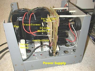
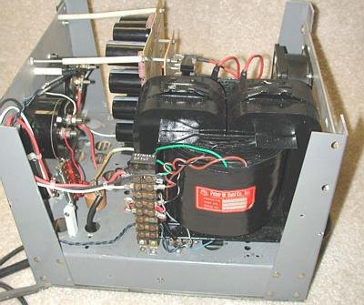
Annotations to the Drake L4B/8877 Retrofit III
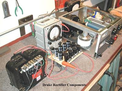
Drake Power Supply
Prototype
Bench testing the Peter Dahl Hipersil with the
complete full wave bridge rectifier
board. This downsized, homebrew
6x8” PC component contains the 10
filter caps (330mFd@ 450VDC), the bleeders and
4 diode rectifier modules
supplying 3300VDC@ 1 amp. In the background is the partially completed Drake
L4B/8877 deck. The 8877 is pictured with the teflonä chimney and an Eimac HR-8 heat dissipating plate cap
machined to fit the larger 8877. A high volume squirrel cage fan has been
repositioned on the chassis . The VOM scaled to 5000VDC is showing about
3600VDC with no load. The ALC switch( front panel lower left) has been replaced
with a mini rotary on/off switch to control the amplifier standby. The ALC circuitry has been removed.
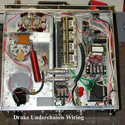
Drake 8877 Tube Socket
The 8877 air system
socket is positioned in the front panel area once occupied by one of the two
3-500’s. Exciter RF is fed to the input circuit and then to the
filament/cathode via the large brown mica capacitor. The OEM tuned circuit blocking disc capacitor has
been reassigned to series feed the second
filament leg. The loose red wire in the foreground will be connected to the pair of 12VDC
zeners for biasing. They have not been
installed as yet. Note the thin gauge aluminum plate used to block off the two
sockets and the fan inlet. A new hole was cut into the pressurized compartment
to accommodate the higher volume/larger fan. High voltage is fed to the plate choke in the upper chassis via the HV
wire and porcelain feed-thru. A small diameter 10 turn hombrew auxiliary choke (tuned ) is
positioned in series with the HV line and visible near the bifilar.

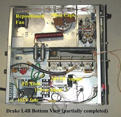
Drake Underchassis
View of the under chassis with several of the circuit changes necessary
to accommodate the new tube. Beginning
at the upper left (front panel) the two toggle switches have been drilled and
pinned and work as a DPDT unit to control the newly installed and
dedicated 115VAC input to the deck. In
front of the switch and slightly to the left is an auxiliary DPDT 12VDC relay
(wired in tandem with the antenna relay coil). On transmit, one pole switches
in the red front panel lamp and the other pole connects the biasing
zeners to the power supply B- via an
interconnecting cable. A small 115VAC 12VCT transformer behind the terminal
strip provides power for the accessory 12VDC relays. The terminal strip is a
convenient tie point beyond the
switch and fused 110VAC line. All 115VAC accessory items including the fan,
rectifier, filament transformer, and
time delay relay all get power from
this point on power up. Because of the over current, the OEM Drake filament
transformer has been replaced with a dedicated 115VAC Thordarsen rated at 5VCT@ 10 amps. The heavy green
filament wires connect directly to the two feed- thru capacitors and beyond to
the bifilar choke and filaments. The RF
sampling PC metering circuit board has been left intact but a heftier 12VDC
3P3T antenna changeover relay (lower left) has replaced the old unit. On
transmit, the middle NO conductors of this relay switch in the filament
transformer center tap to the Drake small PC metering board and multi-meter front panel switch. All other wiring in this section remains
original.
Rear Panel
Note the installation of the smaller Amphenol multi-pin socket and
adjacent fuse in the space originally occupied by the OEM socket. 115VAC is
brought into the deck via this plug. The OEM fan has been replaced so the rear
panel opening has been blocked off. HV from the power supply is brought into
the deck via a HV wire. An old fuse assembly was gutted and drilled and
provides a neat (and cheap) insulated
HV feed thru and strain
insulator. The ALC jack has been wired to control the antenna relay from the
exciter.

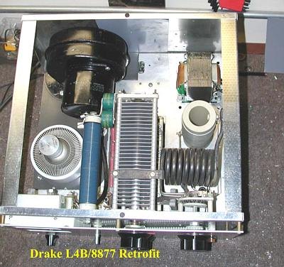
Drake L4B/8877 RF Deck Overview
A view of the 8877
tube placement and the high volume
squirrel cage blower. The newly wound homebrew HV porcelain plate choke is
positioned and bolted horizontally to
the inside front panel. Visible are
pair of 1000pFd blocking doorknobs and a 10 ohm 10w “glich” resistor in series
with the HV line and positioned on the choke underside. The dedicated filament
transformer is correctly rated for the tube so filament over voltage is not an
issue. High voltage is passed through the chassis via the porcelain feed-thru
and directed to the front panel end of the HV choke. Note the use of thin gauge
aluminum plate to block off the opening for one of the tubes and the
original fan not used in this
project. The air system 8877 tube
socket with grid to ground tabs was positioned
over one of the blocked 3-500
holes and mounted to the chassis and
aluminum. after cutting out an appropriately sized hole.
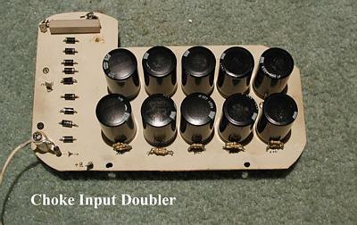
Component Downsizing A 4KV Homebrew Power Supply
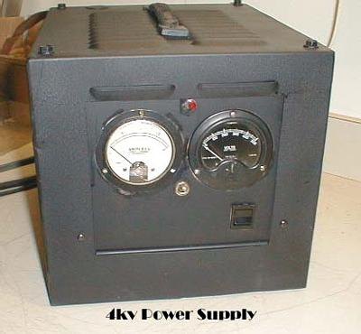
Some old timers would argue that the vintage rack mount (and spread all
over the place) homegrown power supplies were more robust and forgiving than
their latter day counterparts. Perhaps so, but without question they were
aesthetically intimidating and horrendous in size! As an alternative to the
boat anchor supply, consider this “big gun” rectifier board construction
technique utilizing both integrated and
mini-components to achieve high power state of the art results in a
fraction of the space and at a minimum of cost.
To ensure marital tranquility, I made the solemn vow that the radio
shack I planned to build in a newly purchased second home in Pennsylvania would
in no way resemble the disorder and chaos that had (and still does) existed at
the home QTH since 1962. The deal with the XYL was that the room had to be
painted, carpeted, and decorated with curtains on the windows. All the exciters
and amplifiers would fit on a neat and orderly desk, no wires dangled from wall
to wall, and above all no rat’s nest of parts spread over the floor.
Apparently, that last requisite had something to do with facilitating the
vacuuming chore. The first part of the
agreement was easy! I’m the consummate home handyman, and no aspect of the
construction was beyond my skill level.
I was starting from scratch in an unfinished basement, and during my ham
career, I assimilated a great deal of knowledge about finessing a shack since
my humble amateur radio beginnings. At that time, the Spartan setup in New York
City consisted of a length of extension cord hung from the pull chain basement
ceiling receptacle, a wobbly folding card table, a random length of wire for an antenna, an ARRL Handbook
modified Command Set transmitter, a surplus
J-37 key and a brand new state
of the art Drake 2B receiver with the
companion Q-multiplier. Admittedly, it was an eyesore but it did work in most
part to the Drake receiver. To ease
matters a bit with the new shack, the newer generation radio equipment is
admittedly more compact and attractive and appealed to my wife’s sense of, and
need for, order and design in our personal universe. What caused me the
greatest consternation was the array of heavy duty military surplus components
that had been accumulated over the space of several years that would ultimately
dictate the size of the amplifier power supplies I planned to construct.
Consider the self-imposed space constraint dilemma I faced when I began bolting
together a potpourri of parts for a 4-1000A amplifier that included a 6KV “pole
pig” four 866’s (later 3B28’s) and multiple filament transformers in full wave
bridge. Add to that two giant 3000VDC GE 120uFd filter capacitors, six 100 watt
bleeder resistors, a 2amp smoothing choke, and a 20amp Varian. Obviously, it
was physically impossible to fulfill my promise to keep things neat, compact,
and unobtrusive with that array of monster components. Admittedly, I wasn’t totally successful at
the outset. Fortunately, my wife turned
a blind eye to the early endeavors. Apparently she recognized my efforts were
honorable and she fully realized that I was well intentioned; and faithfully
attempting to fulfill our bargain.
However, with each completed project, the rack mount units, standing tall but
ominous, were looking more and more professional but not necessarily smaller. I imagine that those results could
be construed as progress in a figurative interpretation of our agreement. In any
event, the building techniques continued to evolve and were refined with each
completed unedertaking. Projects looked good but the size impasse remained. In
time and only with the advent of the new technology, providing smaller and
smaller components with equal power handling ratings, could amplifier power
supplies begin to downsize. The rest is history! Consequently, in very small enclosures, I was eventually able to
achieve the heavy duty plate voltage requirements I needed for maximum output
from the new generation ceramic tubes
in ever decreasing packages. I’m reasonably certain that these
circumstances are not unique to a large number of hams. If by happenstance you can relate to my
domestic dilemma, or you simply would like your homebrew power supply and
amps in a small packages, consider this
rectifier board construction project as the first step in that rewarding endeavor.
Where to Begin?
Without a doubt, the most difficult aspect of home brewing any project
is ferreting out the components on the parts list. A single inexpensive source
of supply would make great sense logistically, but one does not exist. Hamfests, internet inquiries
and tuning into the Horse traders’ Nets all help a bit with discrete parts, but
that’s time consuming. Recently, I found that several $$ friendly electronics
catalog retailers have solved a portion of my component gathering problems at
least with the rectifier board portion of this project. The parts I needed were
depicted in their catalogs along with size and power ratings and available
within days with only a toll free call and some exchange of payment and
delivery information. For those of you without a junk box inventory, a
suggested list of suppliers is available at the conclusion of the article for
your convenience in getting this project off to a jump start.
How Difficult Is It To Build?
For those radio amateurs who at one time or another considered the building of a homebrew power supply may have asked themselves whether or not they’re capable of
successfully completing a similar
project with only some rudimentary
workshop tools! Couple that with
an understandable reluctance to address what may seem to be an intimidating
undertaking could easily cause you to relegate this and similar postings to the internet twilight zone via the delete
key. Hold off on key stroke at least until you read the article. For the time being, consider yourself a
student back when and get ready for a trade school shop lesson. Take it from seasoned vocational/technical
school educator, teacher, administrator and college adjunct that your concerns
are unfounded and success is assured.
Specialized tools are not a requirement, and even a moderately competent
degree of soldering gun dexterity qualifies you for the undertaking. You’ll
find that the construction details of the two circuit boards (full wave bridge
and doublers) are discussed in depth and illustrated with annotated photographs
and diagrams. Give the project a chance and reconcile yourself to a new and
rewarding dimension of amateur radio equipment building. Take a deep breath and
make the initial plunge. You’ll find you’re amongst a unique group of kindred
spirits.
What’s First To Do?
Every amplifier power supply project begins with a first step! Start by
assessing your anticipated voltage and current requirements to ball park the component parameters. Apply a few
rudimentary rules of electronics to determine both the number and value ratings
of those parts. You’ll need to purchase filter capacitors and diodes based on
the specs of your tube(s) of choice, the power output you’d like to achieve,
and ultimately match it to a plate transformer providing the correct voltage
and current to meet those needs. For
our project, we’ll assume a lineup of parts to safely handle 3600-4000VDC@
2amps and a small footprint Hypes
transformer rated at about 3000VAC
(center tap not a requirement). Other
than the selection of the transformer and (especially) its current carrying
capabilities, there’s no substantive increased cost involved to overbuild the
rectifier components at this juncture. Don’t
be concerned if your voltage and current requirements are only moderate for the time being. However, I’d suggest you go for broke with
the transformer purchase. As a result, you’ll be set for life In this case,
more is better and not at all wasteful or frivolous. Keep in mind that power
supplies are both portable and adaptable and even though RF decks come and go,
a well built supply can be easily reconfigured to meet any new amplifier need.
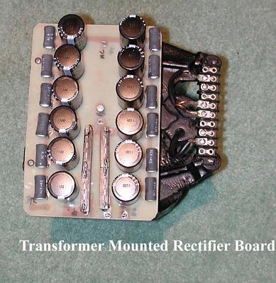
The secret ingredient to the rectifier board downsizing strategy is the
availability of high capacity, inexpensive, minimum profile capacitors rated at
330uFd@450VDC (85degree heat rating tolerance) each measuring approximately 1”
in diameter and about 2” in height. Ten (10) series installed capacitors
(10x450VDC) provide for the 4500VDC upper level of rectified high voltage that
can be safely handled from this lineup. Simultaneously, 33uFd of filtering is
achieved from the series installed placement of these components within the
circuit. That value is more than
adequate for even the most aggressive, current demanding amplifier decks. The
rule is simple! Voltage maximums are additive when series installing
capacitors. Conversely, the level of filtering capacitance is decreased in the
series circuit to a nominal value equal to the number (in microfarads) achieved
by dividing the capacitance of a single unit by the total number of capacitors
in that circuit (330uFd/10=33mFd). It’s
an uncomplicated computation (especially in this project using 10 units) and it
works in every application. The
selection of the discrete 1N5408 diode
(1KV@ 2amps) offers no problem whatsoever. However in later projects,
I’ve elected to use an integrated diode unit for its low cost and ease of
mounting;; but more importantly for its small footprint. Each of the four modules I generally use
are power rated at 4000VDC@ 2 amps
and contain four (4) encased series
installed diodes individually rated at 1000VDC@2amps. One of the units
theoretically would be sufficient (barely) for our needs; however, spreading
the load equally over the four components (16 diodes in total) further reduces
the danger of overloading any one of the diode modules.

Let’s Get Started!
A facsimile template is provided both for the capacitor mounting board
and the diode sub-chassis. Scale your computer printer for a 6x8” overall
size. Center a sheet of carbon
(transfer) paper and the template directly on the copper face of the board and
tape the corners to prevent movement. Transfer the printed circuit to the
copper foil by tracing the images off the template. Use a ruler to keep the lines straight. Carefully mark off the
component mounting holes. Use the actual part to double check the index marks.
Holes will be drilled at these precise points at a later time. Apply a thin
coat of clear nail polish (or one with color if you prefer it more decorative)
with the applicator brush in the cap to carefully seal off the area within the trace lines. Keep in
mind that any copper foil that’s unprotected will be etched when the board is
placed in the chemical bath. If your
hand is a bit unsteady, straight lines can be maintained with some masking
tape. After allowing for drying, a second coating is suggested to ensure
complete coverage. There are a couple of caveats to keep in mind when using a proprietary etching solution. The
liquid copper enchant is not inherently dangerous, however, I’d suggest that
you use eye protection and surgical gloves. Move the process outdoors at this
time for better ventilation. I opted
for the ready to use Radio Shack Enchant Solution (276-1534) containing ferric
chloride FeCl3. It’s cheap and readily
available. Use a Pyrex™ flat bottomed
glass receptacle sufficiently large to contain the entire board. They’re
available at the houseware store located in any mall. Under no circumstances
use your better half’s cookware for obvious reasons! Pour in an amount of
enchant solution that covers the boards completely. Place the smaller board on
top and keep the copper facing up so you can monitor the progress. Processing time varies from 30-40 minutes.
Etching is like watching the grass grow so have a book handy. While reading,
use the other hand to keep the solution in motion to ensure coverage and equal
processing over the entire board surface.
The enchant will stain so don’t wear you Sunday best. Spread some
newspaper or a plastic drop cloth on the floor just in case. You’ll find that
the copper mysteriously disappears first from the edges of the board and
migrates to its center. As the copper is removed from the unprotected areas,
the solution will turn a dark color and thicken in consistency. Remove the
board only when it’s free of all traces
of copper. Avoid over processing since enchant will eventually seep under the
sealant and nibble away at your straight lines. When the boards are free of any
unwanted copper, rinse them in fresh water to stop the chemical action. You’re
ready for the next step.
Use a 5/64” drill to make the holes that support the capacitors,
resistors, and the jumper wires. The faston crimp type terminals were selected
for their quick disconnect feature. They require a larger diameter hole
(5/32”) because of its larger diameter mounting base. Here’s a hint!
Use a needle nose pliers to reduce the size of the fasten base to fit
that hole. The base is split and can be easily folded in on itself to reduce
its diameter. If necessary, you can also use the drill to ream the hole
slightly. The fasten positions on the
board are easily recognizable because they have a larger circular areas of
copper surrounding the respective mounting holes. Once the holes are drilled and tested for fit, use some lacquer
thinner to thoroughly remove the nail polish sealant. If you use regular nail
polish remover, keep in mind that it contains oils to protect the skin from the
harsh chemical. That oily residue may prevent good solder joints. Use a fine
grit sandpaper or some steel wool to thoroughly clean all the tracings in addition to both the capacitor tabs. Mounting the components is not difficult.
However, it’s extremely important to keep the polarity of the capacitors in a proper
series installed alignment. The negative terminal is clearly marked (-) on the
outside cover with a vertical band .
Begin the installation from the (+) end of the board and press fit each
of the capacitors in place. The negative band should face away from you. If the hole is slightly misaligned,
ream the opening slightly with
the drill. After installing the 10 caps
in series, you should end up with the negative terminal facing you and in the
negative position on the board. If the polarity alignment checks out OK, and the capacitors are
pressed flush to the board, solder each
of the tabs in place. Use a dab of flux to ensure a good bond. Double check to
make certain that each terminal on the capacitor was sufficiently heated to
allow the solder to flow from the tab to the trace. Concentrate the soldering iron heat equally on the capacitor terminal and the adjacent foil. You
don’t want cold solder joints here. Use a razor blade to clean the surface of
the bleeder resistor wires before installing.
Form each of the bleeder resistor legs to fit in its position across the
individual capacitor and solder. If you opted for the somewhat longer 15w sand
type bleeder resistors (see parts list discussion), you’ll need to alter the
end to end component alignment of the individual resistor with a slight offset
to make room on the board. Double check
end clearances before clipping leads.
Snip the ends close to the board after soldering in place. These series
wired components bridge the high voltage to ground. They will safely discharge the high voltage
stored in each of the capacitors when the supply is shut down. If you’re using
either the fasten male of female connector (rather than direct soldering), it’s
important that each terminal is seated into the hole well up to its shoulder. If it’s not in this fully seated
position, downward pressure on the
fasten with the mating connector may lift the foil from the underside Orientation
of the fastens is not critical except
for the 8 female connectors on the diode board. The rectifier diodes
will only snap into place if the fasten units on the board are
properly aligned. Connect a HV insulated jumper wire across the two diode
board negative terminals to complete the full wave bridge circuit. Wire in jumpers from the positive and
negative terminals on this board to their respective terminals on the capacitor
board in order to integrate the circuits.
Center the diode board foil side to foil side and attach it with four
(4) ˝” insulating spacers. Position the
spacers so as not to interfere with any of the traces on either surface. To
complete the project, wire in a 50 ohm
10W resistor between the B- and
the chassis ground terminus. Make certain to remove all traces
of the flux with an acetone. This precaution eliminates the possibility of a HV
short circuit across the trace via the flux residue. At about this time, it would be appropriate to sit back, relax with a cool drink, and
enjoy the fact that you’ve completed a job that’s well done. You should be
content with the thought that you’re well on your way to completing a practical
and rewarding project. The rest of the amplifier project, reserved for the next
step in the process, is to locate a suitably sized enclosure and to bolt
together an array of parts to control and monitor your rectifier board.

Food for Thought!
You may want to give some serious thought to eliminating the diode
board completely and incorporating it
into the center of a single board.
Several of the digitals depict this technique both in the doubler and full wave
bridge projects. You may want to lengthen one trace a couple of inches on one
side and the top to allow a bit more room for those components. Based on my
experiences, I decided in later
projects to keep things as compact as possible and opted for the diode modules
on the single board. However, the
decision is yours. Keep me informed if
you come up with some interesting adaptations. Incidentally, if you’d like to
see the completed home away from home
Pennsylvania shack, check out QRZ.COM and dial in my call.

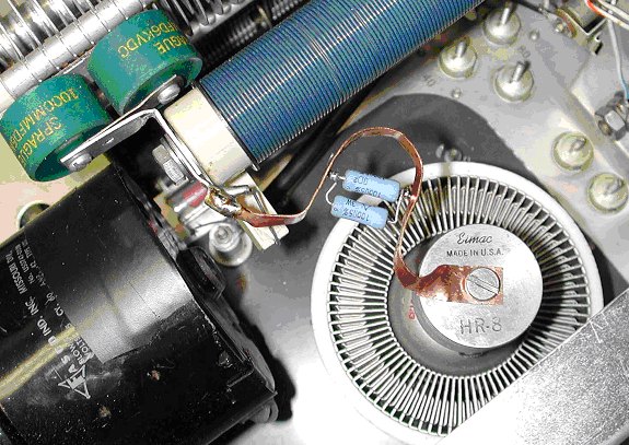
Drake L4B/8877 Parasitic Choke Assembly
A view of the parasitic choke assembly utilized on the retrofit project. The
resistors are paralleled 100 OHM
3 watt resistors nested in a “U” shaped
half loop. I’m not certain why, but this configuration seems to
work more effectively than the typical 3 turn flat stock coil with the resistors on the
inside. The HR8 heat dissipating plate cap was machined on the lathe to increase
the opening to accommodate the larger diameter cap on the 8877. Does a
nice job! To handle the current, a pair
of paralleled 1000pFd blocking capacitors were used. Note the very short leads
connecting up the various components.
This was accomplished by horizontally mounting the HV plate choke to the
inside front panel by carefully positioning it to ensure short leads; but at
the same time far enough from the chassis
to prevent arc over. The blue decorator color
enameling on the #20 gauge wiring on the porcelain rod was a
nice touch aesthetically but in
no way enhances the power output. The sand type glich resistor series installed in the HV line and visible beneath the choke is rated at 10
ohms at 10W. Immediately below the resistor and slightly to the left is the
porcelain feed-thru mounted on the
chassis. The heavy looking black wire moving under the choke and to the right
is the HV spark plug wire connecting HV from the feed-thru to the front panel end of the choke.
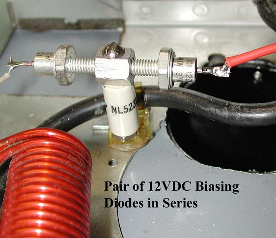
Zener Biasing The L4B/8877
Series mounting a pair of 12VDC 10W
zeners for biasing the 8877 is a relatively simple process especially if
you’re able to locate comparable units with one threaded base the cathode and the other base the anode. Pre-drill a threaded spacer for a mounting bolt. Screw in the zeners for
the series connection and “T” Mount the entire assembly on a porcelain
standoff. Mark the direction of the
cathode end (bar and arrow ) and wire
that side to the cathode/filament tie
point of the bifilar choke on the
filament transformer side. The other end (anode) is wired to the B- on the rectifier board through a pair of normally open (NO) contacts on the auxiliary relay that closes on transmit.
On key down, the B- is directed
to the zeners through the closed contacts on the relay.
Parts List
All Electronics 905 S. Vermont Street Los Angeles, CA 90006 1-800 826-5432
www.allelectronics.com
10 capacitors 330uFd@450VDC
# EC3345 $2.75 each
High voltage wire TLW-1 18 gauge 30KVDC $.30 per foot
Copper Clad Board 6”x12” #PCB-612
$5.00
Ľ” faston connectors: male #2325 50/$3.00
female #1325 50/$3.25
Threaded insulated standoffs
SP120 10/ $.75
Marlin P. Jones Box 12685 Lake Park, Florida 33403 1-800 652-6733 www.mpja.com
4-
Rectifier
modules 4000VDC@2 amps #5071-D1 $2.50 each
Radio Shack
PC Board etching solution
#276-1576 $3.49
Wire wound resistors
50ohm@10W #271-133 2/$1.49
Ameritron 116 Willow Road Starkville,
MS 39759 1-(662) 323-8211
www.ameritron.com
10 bleeder resistors 50K
ohms@ 7watts (#103-7580) $1.75 each**
:Tech America Box 1981 Ft. Worth, Texas 76101-1981,
1-800-877-0072, www.techam.com 10
Sand type bleeder resistors (#900-1257)
51K@15W 1-9 $.60 ea. (10+ $.54 ea.)