FT-1000D Key Click Modification
The FT-1000(D) runs an essentially unshaped CW waveform into the filters. This harsh signal generates unnecessary key clicks. The clicks are strongest from almost 1 kHz below to 2kHz above the transmit frequency.
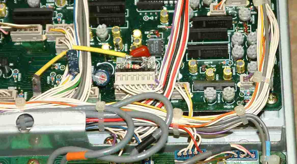
Locate the seven-pin connector J3024 at the middle-front of the AF board. (The AF board is the one with the audio, PTT, ALC, and key jacks as well as other connectors.)
This is a picture with a hand-wired mod in place.
Cut the wire going to pin 2 T CNTL). This is the second terminal from the right (front of radio viewing). This is NOT the lead with 9 volts (nine volts is on pin 6). If you are unsure you counted the correct direction, measure the voltage!
Connect the collector of a 2N3904 to the flying harness wire you just cut.
Connect the emitter towards the jack on the wire you just cut. This transistor MUST be a 2N3904.
Connect a 1.5k resistor from collector-to-base on the transistor.
Connect a 10uF, 25-50 volt capacitor from base to ground. A non-polarized capacitor may be better if you can find one. No one has reported problems with normal electrolytics as long as the positive lead connects to the base of the transistor. For QSK operation use a 5uF capacitor.
The Results:

This modification slows the waveform rise and fall times at Q3030 and D3009. The result is a normally sloped CW waveshape into the SSB filter.
This is a nearly-perfect waveform with about 7mS fall and 4ms rise. The important thing is there are no sharp edges that cause clicks!
Clicks beyond 1 kHz above and below the transmitting frequency move into the composite transmitter noise, and there is about 50 dB reduction in clicks on some radios above the TX frequency!
Clicks 500Hz away are reduced about 20-35dB.
There is almost no change in "keying sound" on the transmitting frequency. The envelope shape is near ideal, and bandwidth reduction is dramatic.
Operating
Warning: This mod is NOT compatible with QSK with the full 10uF in circuit. For QSK use, I suggest adding a SPST switch from the 10uF capacitor to ground. You can place an additional 10uF capacitor across that switch, or simply add an additional 10uF in series with the ground lead from C1 ( this gives 5uF total value at the base of Q1) and not switch the system. When not operating QSK, I recommend using the full 10uF of C1 for the cleanest signal.
The ideal wave shape occurs when the ALC is at the upper area of the blue ALC line on the FT1000 meter. With full DRIVE, adjust for desired power with the RF PWR control. After achieving desired power, back the DRIVE down until the ALC indication just starts to move away from full blue area (half-scale). Anything from 1/3 to 1/2 scale is a normal waveform.
For lowest clicks, adjust DRIVE until ALC until it just registers (perhaps 1/8 to 1/4 scale on ALC).
Note: this modification was developed by W8JI for his FT-1000D and originally posted
to the Topband reflector.
The problem:
Good engineering dictates never running a square rise and fall waveform into a crystal filter.
The square rise-and-fall waveform will cause filter ringing.
The FT-1000(D) runs an essentially unshaped CW waveform into the filters, generating
unnecessary keyclicks that are strongest from almost 1 kHz below to 2kHz above the transmit
frequency.
The cure:
Locate the seven pin connector J3024 at the middle front of the AF board. The AF board has
audio, PTT, ALC, and key jacks as well as other connectors.
Cut the wire going to pin 2 (T CNTL). This is the second terminal from the right (front view).
This is NOT the lead with 9 volts (nine volts is pin 6)!
Connect the collector of a 2N3904 to the flying harness lead, and the emitter towards the jack.
Connect a 1.5 k resistor between the base and collector, and a 10 uF 25 capacitor from base to ground.
I forgot to say the resistor goes between the collector and the base of the transistor.
The transistor turns on slowly because the 10uF capacitor charges through the 1.5k resistor. The stage turns off slowly because the
capacitor discharges through the base to the emitter.
The Results:
This slows the waveform rise and fall times at Q3030 and D3009. The result is a normally sloped
CW waveshape hitting the SSB filter.
This reduces clicks beyond 1 kHz above and below the transmitting frequency into the composite
noise of the transmitter, about 50 dB reduction in clicks on my radio above my TX frequency.
Clicks 500 Hz away are reduced about 35 dB.
There is almost no change in "keying sound" on the transmitting frequency. Very little change
in envelope shape, yet bandwidth changes are profound.
73, Tom W8JI
K1ZM's installation notes:
I did as Tom said and cut the wire going to pin 2 on J3024 (this is the
second pin from the RIGHT) when viewing this connector with the radio upside
down with the front panel facing toward my chest.
You want to follow this wire into the harness and cut it so as to leave about
1.25" of wire remaining on pin 2 of J3024. Then pull the harness side of the
wire out carefully to expose a similar length of wire.
I made up a little "jig" of the 2N3904, with the 1.5k 1/2 watt resistor
connected between the base and the collector of the transistor - and tinned
the emitter to accept a "tacked on" connection.
The third component required is a 10UF electrolytic at 25v, the negative
side of which must go to ground. Perhaps not the NEAREST point - but
certainly the EASIEST and most accessible point at which to find chassis
ground and mount the cap is at a mounting screw for the AF board in the
middle of the board on the front panel side. This is about 2 inches to the
LEFT of where the cut wires wind up - and it is also an open area allowing
plenty of room for the cap to float above the board.
I chose an axial lead cap for this project (largely because its long leads
were useful to me in spanning the distance involved) and mounted it flush
onto a solder lug. This I placed under the board mounting screw noted above -
negative side of the cap almost directly on the lug. Then I dressed the
positive axial lead with sleeving and passed it UNDER an intervening wiring
harness in order to get the plus side of the cap into the general vicinity of
where the two wires resulting from the cut to pin 2 at J3024 would reach.
Once this has been achieved, it is a straightforward process to tack the
short wire from pin 2 to the emitter of the transistor and the flying harness
lead to the collector. The positive lead of the 10UF cap is most easily
tacked on last and I should note that it is this lead that suspends the mod
in mid air above the AF board. As an added measure to insulate the mod from
all other components around it, I placed some pvc electrical tape over the
top and bottom of the mod - just in case.
One other point worthy of mention is that it is a good idea to bend the
solder lug up at a 45 degree angle right at the screw to ensure no adjacent
foil traces wind up being jumpered when you tighten the screw to hold the lug
in place. I also aimed the 10UF cap into an open area on the board - where it
just floats out of harms way from nearby components. It is easy to see how
to do this when looking at the board - and also easy to pass the positive
axial lead UNDER the harness to the right in order to make the connection to
the base of the transistor where it meets one side of the 1.5K resistor.