To enable all band transmit, disconnet radio from power source and
disconnect all cables. Remove cabinet, place radio on its tor and locate
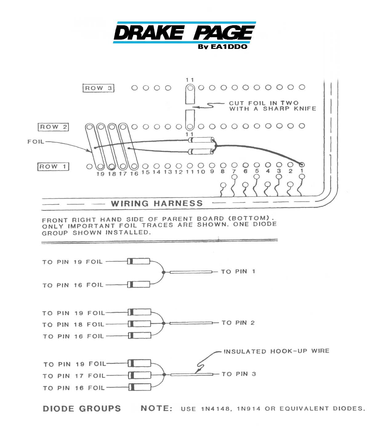
traces show on top portion diagram. Cut the trace associated with pin 11
as show on following page.
Note: Transceiver will not transmit in the 2.5 Mhz range. Attempting to
do so will force the PS-7 power supply into an overcurrent condition.
Low Frecuency Receive Modification
1) If the TR-7 has not been disconnected from all accessories and the bottom cover removed, do so at this time. Turn the radio upside dawn with the front panel facing you.
2) Referr to the attached diagram and identify connector row 1 on the front right-hand corner of the parent board.
3) Carefully label connector pins 1, 2, 3, 16, 17, 18 and 19 in row 1.
4) Refer to the attached diagram and prepare one group of two diodes and two groups of three diodes. Use 1N4148 diodes or equivalent. Connect the anodes of the diodes in each group together and attach a lenght of insulated hookup wire to the common anode connection of each group.
5) Carefully solder the diode groups in position per the diagram. Connect the cathodes of the diodes to the indicated foils and the free end of each lenght of hook-up wire to the indicated connector pin. To avoid shorts, use insulated sleeves as necessary, and dress the leads neatly. Position the TR-7 wiring harness away from areas to be soldered to avoid damage to the harness.
6) If your TR-7 has an AUX7 card installed, be sure that positions 1, 2 and 3 are blank (no programming modules installed).
7) Check again for shorts, reinstall the bottom cover and reconnect the TR-7 to the other station components.
8) Your TR-7 will now receive 0-500KHz in AUX position 3, 500-1000KHz in position 2 and 1000-1500KHz in position 1. (Is is normal for the SET BAND lamp to glow in this mode. Use the 1.5MHz band switch position for 0-1.5 MHz reception).